My favorite set of original notes is titled "The Role of Rotation in Rigid and Deformable Body Mechanics". The abstract in the handwritten version is shown.
I transcribed the first few pages of the rotation notes to HTML format. In doing so, I realized that the best way to complete the task would be to enlist assistance of students. Perhaps I will be in a university environment in future. Here is the HTML example.

The Role of Rotation In Rigid And Deformable Body Mechanics

Abstract

This set of informal notes presents, for what is considered to be the first time, a computational procedure which permits calculation of direction cosines, position of axis of rotation, amount of rotation, and angular velocity when three primary angular coordinates are selected to be the angular positions of body axes with respect to reference axes. The emphasis is on kinematics of rotation for a rigid body with one point fixed, in terms of rectangular Cartesian coordinates. The notes include extension to discussion of the role of rotation in deformable body mechanics, using a linear definition of strain rather than the more usual Cauchy-Green quadratic definitions. Deformation gradients and material time derivatives of deformation gradients are given for linear finite deformations of a sphere and cylinder.

Table of Contents

Paragraph                                    Title                                     Page
                   Abstract

1.                Introduction

2.                Rotation of Body Axes

  2.1        Kinematics Of A Rigid Body
  2.2        Reference Axes, And Body Axes
  2.3        Use Of The Second Scheme of Euler Angles In Deriving Off-Diagonal
               Direction Cosines
  2.4        Restrictions On Choice Of Particular Angular Coordinates
  2.4.1     Sample Calculations
  2.5        Application Of Euler's Kinematical Theorem
  2.5.1     Sample Calculations:α = β = θ

 3.               Time Dependent Rotation

  3.1        The Role Of Time
  3.2        Angular Velocity, In Terms Of Parameter η
  3.3        Angular Velocity; Axis of Rotation Known
  3.4        Angular Velocity; Angular Coordinates α,β, θ Known
  3.5        Rates Of Change Of Elements Of The Array a
  3.6        Analysis Of Errors In Measurement
  3.7        Sample Error Analysis Results

4.                Rotation Tables

  4.1        Conversational Programming System Application
  4.2        Developmental Calculations
  4.3        Direction Cosine Tables; Fixed Axis
  4.4        Direction Cosine Tables; Precessional Motion

5.                Recommendations For Future Work

  5.1        Direct Applications
  5.2        Logical Extensions
  5.3        A Program Of Applied Research, For Definition of Engine Disk
               Production Controls

6.                References

                   List Of Tables

Table                                            Title                                     Page(s)

  1.          Description Of Three Rotations Of Body Axes: α = β = θ;
               α1 = 45, α2 = 90, α3 = cos-1(-1/3)
  2a-2c.  Description Of Three Rotations Of Body Axes: Error Analyses For
               α = 0; β = θ= 0.1, β = θ = 10.0
  3a-3c.  Direction Cosines: α = β = θ, β Varied From 1.0 To β = cos-1(-1/3)
  4a-4c.  Summary Of Euler Angle Coordinates: β Varied From 1.0 To
  cos-1(-1/3)
  5a-5h.  Angular Coordinates: α = β = θ, η From 1.0 To 359.0
  6a-6h.  Direction Cosines: α = β = θ, η From 1.0 To 359.0
  7a-7d.  Angular Coordinates In Precession: ζ From 1.0 To 180.0
  8a-8d.  Direction Cosines In Precession: ζ From 1.0 To 180.0

1.0 Introduction

Many occasions arise when structures and materials engineers require analysis tools for description of the rotational components of motion or of position in test objects. On a large scale, structural components of a proof test aircraft undergo large rotational motions, in addition to translation and deformation. On a microscopic scale, identification of crystallographic orientations and textures in structural alloy specimens hinges upon ability to characterize relative angular positions.

These notes explain, in simplified fashion, how to describe the rotation of an idealized rigid body with at least one point fixed in position with respect to a rectangular reference frame, with axes X, Y, Z. A second rectangular, frame with axes x, y, z, has the same origin of coordinates as does the reference frame. Only angular motions of x, y, z, embedded in the body or attached to it in a rigid manner, are considered.

Preparation of the notes began in March 1974, with an attempt to show a Lockheed Continuing Education class how the angles between axis x and axes Y, Z, axis y and axes Z, X, and axis z and axes X, Y can be derived expicitly in terms of angles between pairs of axes (x,X), (y,Y), and (z,Z). The attempt was a failure. It was noticed, however, that when the last three angles are regarded as a primary choice of angular coordinates, and one of the sets of three angular coordinates defined by Euler is used as an intermediate choice, the intermediate coordinates can be expressed in terms of the primary ones, and then the six remaining angles between x and Y, Z, y and Z, X, and z and X, Y can be defined impicitly as functions of the primary angular coordinates by means of the intermediate Euler coordinates. Details of the procedure can be submerged in a computer program designed to give the outward appearance in terms of numerical input and output that the analysis of rotation is being handled only in terms of the primary choice of three angular coordinates.

Analytical description of rotation of axes x, y, z with respect to axes X, Y, Z is easier to understand and more readily visualized than is the case with description in terms of any set of Euler's angular coordinates. For example, consider the following model used repeatedly during preparation of these notes. Mount a rod on an equilateral triangular base. Label the apices of the base as x, y, and z and the three edges at the corner of a room as X, Y, and Z. Place the base at the room corner so that the three angles between the rod and the edges X, Y, and Z are identical, and x is at X, y at Y, and z at Z. Treat the rod as an axis of rotation with respect to X, Y, and Z. Rotate the rod through 120 degrees, and notice that x is at Y, y at Z, and z at X. Select any set of Euler's angular coordinates from a textbook, and try to estimate values of the Euler angles in comparison with the primary angles for various rotations of the rod.

For a particular rotation of axes x, y, and z with respect to axes X, Y, and Z, it is usual to represent the nine angles between the two sets of axes in terms of a square array of nine direction cosines. When successive rotations are treated as products of direction cosine arrays it is found that the resultant rotation is dependent on the order of component rotations, unless each direction cosine array represents a so-called infinitesmally small rotation. As a consequence, much of the elementary literature on rigid body rotations emphasizes the theory of small rotations. These notes do not make small angle assumptions. The relations presented in Section 2. can be used to describe the orientation of axes x, y, and z in terms of the primary choice of angular coordinates, regardless of the order in which component rotations might be performed. Direction cosine arrays describing component rotations are not multiplied. Instead, bookkeeping is performed on the values of the primary angular coordinates. The direction cosine array for the current sums of the angular coordinates correctly describes the current orientation of axes x, y, and z.

A straightforward discussion of time dependent rotation in given in Section 3. Sample numerical results for six cases where the effects of misalignment on measurement of rotations are presented for the interest of engineers responsible for inertial guidance system installation and calibration. Remote terminal Conversational Programming System (CPS) techniques were applied to derive numerical results tabulated in terms of primary and intermediate angular coordinates, direction cosines, orientation of axes of rotation, and rotation magnitudes. These results are summarized in Section 4.

Recommendations for direct application of the rotation relations are given in Section 5. An outline is presented also of the role of rotation in deformaable body mechanics. Examples are used to demonstrate the simplicity of linear strain relations when no assumptions are made concerning the magnitude of deformations.

2. Rotation Of Body Axes

2.1 Kinematics Of A Rigid Body

Kinematics of a rigid body concern the effects of motion, as opposed to causes. How a body moves is studied, without explicitly describing why it moves. The motion of a body is discussed often in terms of the motion of its center of mass. albeit the concept of mass does not belong properly within the framewprk of kinematics.

A rigid body considered to be isolated from all others has six motional degrees of freedom, three of which describe translation of the center of mass, and the remaining three describe rotation about a point fixed at the center of mass. Orientation of a body of arbitrary shape can be defined in terms of three mutually orthogonal axes embedded in the body. Let the origin of the three body axes be located at the center of mass, and treat rotation of the body as rotation of these body axes.

2.2 Reference Axes, And Body Axes

Let x, y, z represent body axes, and refer rotations to fixed reference axes X, Y, Z.
axes        Rotation of x,y,z about fixed point O, referred to fixed axes X,Y,Z can be described completely by keeping track of the angular positions α, β, θ.

For example, assign unit vectors to the positive directions as follows: êx, êy, êz in positive directions of X, Y, Z and îx, îy, îz in positive directions of x, y, z.

Then îx = cos(x,X)êx + cos(x,Y)êy + cos(x,Z)êz,
          îy = cos(y,X)êx + cos(y,Y)êy + cos(y,Z)êz,
          îz = cos(z,X)êx + cos(z,Y)êy + cos(z,Z)êz.
The three diagonal elements of the direction cosine array

a matrix equation

are just a11 = cos(α), a22 = cos(β), a33 = cos(θ). Consider α, β, θ to be known. The six orthogonality conditions
       îx · îx = îy · îy = îz · îz = 1,     îx · îy = îy · îk = îz · îx = 0
are theoretically all one needs to find the remaining six direction cosines a12, a13, a21, a23, a31, a32 in terms of α, β, θ. My attempts to do so directly have been futile.

2.3 Use Of The Second Scheme Of Euler Angles In Deriving Off-Diagonal Direction Cosines

M. Rauscher, Ref. 1, p. 475, used the term "Second Scheme" to identify Euler's three angular coordinates θ, φ ψ as shown.
Euler's Second Scheme    
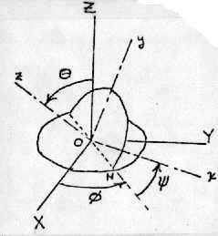
Line ON is called the line of nodes. The position of axes x, y, z can be thought of as having been obtained by the following sequence of rotations:
  1. rotation through φ with OZ fixed,
  2. rotation throuth θ about the line of nodes,
  3. rotation through ψ with Oz fixed.

The direction cosine array a can be expressed in terms of α, β, θ and φ, ψ as follows:

matrix a in terms of 5 angles
    where a11 = cosα = cosφcosψ - sinφsinψcosθ, and a22 = cosβ = -sinφsinψ + cosφcosψcosθ.
    If the case where sinθ = 0 is treated separately, and α, β, θ are considered as known angular coordinates, then Euler angles φ, ψ can be calculated with aid of the formulae

    φ = (cos-1(c + d) + cos-1(c - d))/2 and ψ = (cos-1(c -d) - cos-1(c + d))/2,

    where c = cosα + cosθ(cosαcosθ - cosβ)/sin2θ and d = (cosαcosθ - cosβ)/sin2θ.

    Thus, when α, β, θ are given, Euler angles φ, ψ can be calculated, and off-diagonal elements a12, a13, a21, a23, a31, a32 can in turn can be calculated in terms of θ, φ, ψ.

    I think of given angles α, β, θ as equations of right cylindrical cone sheets, with axes X, Y, Z, respectively; and apices all at the origin O. With this interpretation, rotated body axes x, y, z are particular generators of the cones, such that unit vectors îx, îy, îz define an orthogonal triad. It is not alwats possible to meet the orthogonality conditions for arbitrarily chosen α, β, θ. Whatever α, β, θ values are assigned, the rotation is only proper when the determinant of direction cosine array a satisfies the condition deta = |a| = 1.

    Six of 33 original pages of the rotation notes have been transcribed.

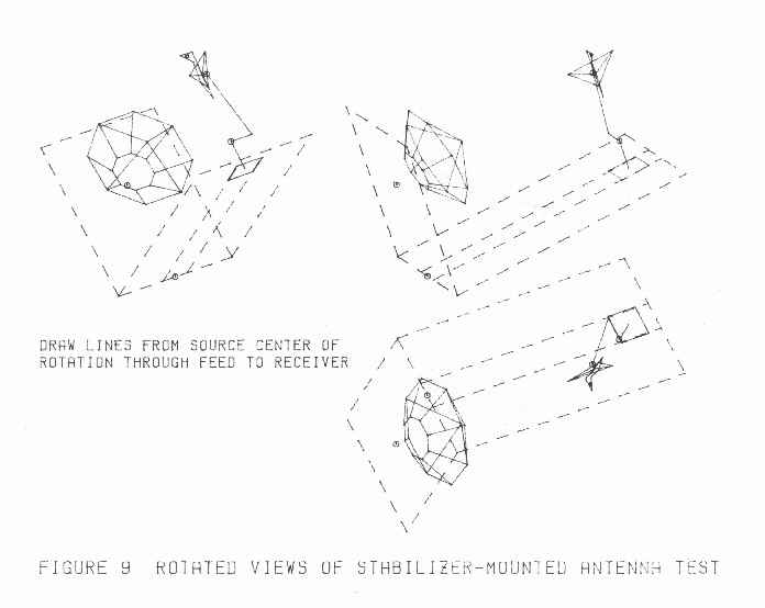
One of the assignments I was given while working at the Lockheed-California Company was to direct research at the Research and Development Center outdoor Antenna Test Laboratory.

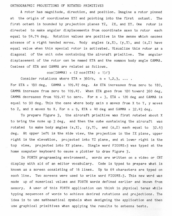
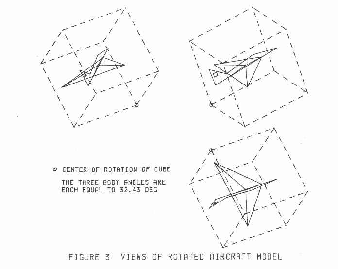
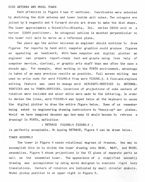
I wrote a technical paper to summarize applications of my rotation theory. The title: "Body Angles and Rotation Arrays in Forth, by Glenn E. Bowie".
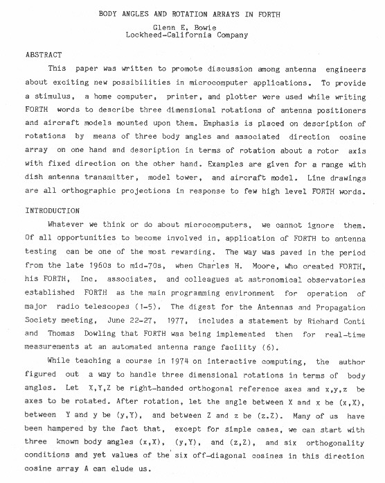
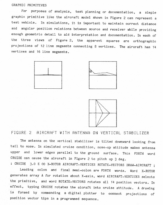
nul no images

my card